SUTD-MIT GLP Summer 2013
Electric Go-Kart Design

Last Burst of Fire: A New Wheel on the Night before the Race

On the night before race day, we had a last burst of fire to change the large wheels to a new wheel

After failing the final inspection on Saturday and Sunday was the race day, we had a serious discussion on what we should do. The vehicle couldn't move with a rider on it because of the insufficient torque that was caused by the big wheels and an insufficient gear ratio. 

We were filled with exhaustion and disappointment but w were still very determined to get the vehicle moving with a rider on it. We've come this far after all.

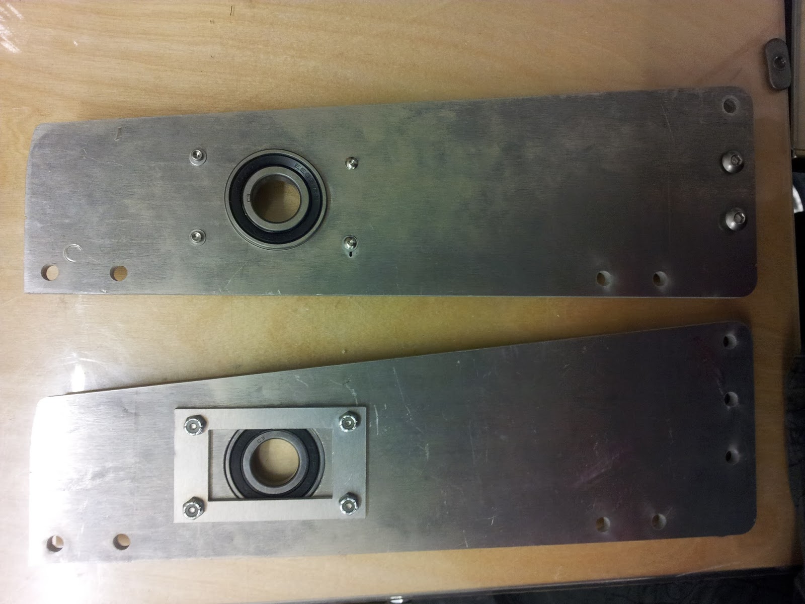
It was another full night of hard work again. We raced against time and fatigue to get a new wheel up by the next day. By morning, we had the wheel up and the whole system was there. The only problem that prevented us from running, was the misalignment of the sprocket. 

The previous sprocket had to be forcefully removed and in that process, the motor axle was damaged. It resulted in an off-centred sprocket that let the chain slip out whenever we tried to drive. By the end of the day, the problem was slightly fixed but still had room for improvement. 
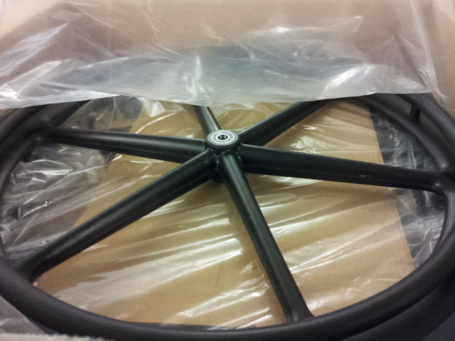
The new wheel was scavenged from the general supplies cabinet. As all the wheels there don't work by themselves, we had to fit parts from different wheels together to get a single working wheel along with the brakes. 


Our vehicle didn't get to race. Yet, I'm confident that our group has experienced many challenging problems and mistakes which allowed us to solve them with innovative solutions that others did not face. Those problems only arose because we tried something new. We weren't trying to be ambitious, we simply truly believed in making something better.

Redefining an electric vehicle was not something we were technically capable of, but we tried our best with our effort and time. Perseverance was put to the test after many sleepless nights where our group was alone in the workshop. There were disputes, but it helped us to improve. There were challenges, but it allowed us to grow and overcome them.


Read more

Finished yet unfinished


On Saturday, we finished our electric vehicle after yet another mad rush. Everything mechanical and electrical were in place. Yet, we failed the final inspection.

The vehicle could not move when a rider was on it due to the large wheels that resulted in insufficient torque. The gear ratio was insufficient to get the vehicle rolling. It appears that the initial calculations were wrong - we needed way more torque to power the wheels.


Read more

The steering problem


Just when we thought that the steering was performing as it should, we had a problem with it becoming difficult to turn back when it was at fully turned.


Read more

Video: Testing the Motor and Wheels off the ground


Read more

Supporting the foot rest

Initially, one of the points that we failed the rolling test was that the foot rest had no metal to support it. Despite the wood being strong enough, it may not withstand the force of a feet stomping on the brakes. We had to cut new joints and new pieces of 80/20 to extend the support to the foothold.


Read more

Night til dawn at IDC - Faulty Throttle

The faulty throttle
When the electrical system was all wired up, I was anticipating the first moment that the motor would spring to life. It didn't.

We had to troubleshoot every individual part of the circuit and test them in isolation to figure our where a mistake was made.

The motor was spinning uncontrollably when we were just testing out the hall effect sensors for continuity. The worst part was that the motor spins even when the throttle was not depressed. This led to several attempts at re-soldering the hall effect sensor. We even burnt our first hall effect sensor and had to replace it entirely.


It was not until dawn when I was perfectly sure that the hall effect sensor should be working fine. I then suspected the throttle. When we wired up a voltmeter to the throttle once again, we found that it now only changes by merely 1V - Charles told us that this was unusual. 

I then unwired and unsoldered the existing throttle and hooked up a spare throttle from the supplies cabinet. We finally had full control of the electrical system. 

Our trials and tribulations were not over yet. That morning when we were all exhausted and dozing off on every possible surface at the IDC, we had to solve yet another major problem...


Read more

The Brakes that didn't give us a break

The Brake Pedal

Brake caliper and mount

When the electrical system was being done, the brakes were being made simultaneously. It took the whole night. It was difficult to find the right tension point and took some teamwork to get it up. Also, we only realised there was a better screw at the end, which made the job much simpler.

Looking back, we should have planned how the brake mounting bracket should be like in the initial stages. We didn't have time to prototype the mounting bracket and had to design it on the spot and rush it to the waterjet. We ended up making more manual cuts and had to file several times to make it work.


Read more

3D Printed Switch


I must honestly say that we failed to plan for a location for the switch. Lucky for us, we were able to adapt and find a neat spot in the front to place the switches. The key switch was 3D printed for better grip as the XT60 may be slightly difficult to pull.


Read more

Solution to the wheels


We 3D printed these stoppers to fit into the wheels to hold it together with the axle. It fit snugly after some hammering and were able to hold the wheels tightly.


Read more

Wiring up the electrical system

Wiring up the electrical system
Soldering the Hall Effect Sensor

Thanks to the collaborative spirit amongst many teams, everyone went from clueless to being able to wire up a working electrical system. The tips given by the first few teams to finish were also much appreciated. It was pretty smooth sailing until...


Read more

Big wheels, big problems


The wheel posed us a problem - how do we mount it onto the differential axle? The hole was too big for the axle and we did not have the appropriate bearings and mounts. We also considered making a hub in the centre for holding the wheel but it wasn't feasble since there wasn't anything to latch onto the wheel.

After much consideration, we ended up drilling two holes through the shaft collar and securing a circular wooden piece on to the shaft collar. The wooden piece used the holes on the rim that were meant for the wheel chair's hand rim to latch on to the wheel.

And this was merely the beginning of our problems...


Read more

The seat!

The night that the frame was laser cut, we stayed up and I managed to string up the seat! It was tied very tautly, considering that I only did it when the sun rose.

Don't you just wanna sit on it? 


Read more

Our 1/2" wood arrives for the frame!


The mahogany 1/2" wood has finally arrived after some delays. Began to laser cut and install the wooden frame.


It wasn't all that easy to laser cut the 1/2" wood. It came 2' by 4' so i had to cut it up to fit into the laser cutter. What's more, it couldn't have been a simple cut into 2 halves - I had to cut in angles so that I could fit both sides of the frames into the wood. I ended up using the jig saw because of its maneuverability which allowed me to cut turn and cut diagonals.


Read more

Wood turns to metal!

Our aluminium waterjet parts have arrived!

The rear wheel support - the rectangular brackets were designed at the last moment to hold down the bearings. As it turns out, the waterjet parts have a certain angle of cut so the openings were quite tricky to file down to the right size for the bearings.

The assembled chasis with aluminium. We were so excited that we stayed up to put it together.


Read more

Prototyping Photos: Starting to fit things together

To keep things up to speed, we decided to prototype the frame as soon as the chasis came up, to see if it all fits together as calculated.


Read more

Prototyping Photos: Steering test


Read more

Prototyping Photos: Chasis made of wood!

The wooden chasis!


Read more

The Frame

The wood prototype of the frame - assembled with shoulder guards


Read more

The Refined Frame!


Our latest frame with a guard
In this revision, guards were added to protect the rider from the wheels.


Read more

Frame Prototype 1: Need to revise!

First prototype of frame and how it sizes up against the wheel
The frame prototype turned out well but apparently the wheel will pose a larger threat than we thought it would. The buffer zone between the rider's shoulders and the wheel may not be enough. After making some calculations with this prototype, we made some revisions to the frame. A guard will be added to protect the rider from the wheel.

How a rider might sit on the frame


Read more

Conceptualizing the frame

Circles - The basis of our curves!
Adding a little more detail. Strings, similar to a harp

More support

Further refining... This will be laser cut on wood as the first frame prototype


Read more

Bending Wood

To test out the technique of bending wood, we tried cutting one to see if it works. We appreciate the e-mail advice from Carolyn (a MIT student who built Zoran when she went through 2.007) to test it out and experiment with how the wood bends.

Laser Cutting
The first attempt of bending - broke
During my first attempt, the wood broke when I applied too much force. I felt that the width of each slit was too thin, causing the breakage. I then begun re-modelling another wood with larger slits and tested it out. I wanted to make sure the problem was not with the pattern or the technique itself.

Bending the 2nd wood
The second attempt turned out pretty well. The wood could be bent for quite a bit but it was still quite stiff in general.


Read more

Our HUGE Wheels have arrived!


Wheel Chair Wheels
We couldn't use bike wheels because they require a fork and it would add complications if we were to motorize it. We chose wheel chair wheels instead as they can accommodate an axle.


Read more

Milestone 3 (Part 2): CAD Modelling

Overview of Assembly CAD Model
Concept art of wooden frame - form created using simple circles


Parts/joints that will be sent to water jet


Read more

Milestone 3 (Part 1): Choice of Parts and Why

Motor:
Turnigy Aerodrive SK3 - 6364-245kv Brushless Outrunner Motor

Turns: 14T

Voltage: 10S Lipoly

RPM/V: 245kv

Internal resistance: 0.018 Ohm

Max Loading: 70A

Max Power: 2700W

Shaft Dia: 8.0mm

Bolt holes: 32mm

Bolt thread: M4

Weight: 718g

Motor Plug: 4mm Bullet Connector

Reason behind Choice: Calculations show that 245rpm/volts is a adequate rating that can drive the go-kart to reach 30km/h under non-ideal conditions.

Controller:
•Frequency of Operation: 16.6kHz.
•Standby Battery Current: < 1mA.
•5V Sensor Supply Current: 40mA.
•Supply Voltage: PWR, 18V to 90V.
•Supply Current, PWR, 150mA.
•Configurable battery voltage range, B +. Max operating range: 18V to 45V.
•Analog Brake and Throttle Input: 0-5 Volts. Can use 3-wire pot to produce 0-5V signal.
•Reverse Alarm, Main Contactor Coil Driver, Meter: <200mA.
•Full Power Operating Temperature Range: 0 to 50 (controller case temperature).
•Operating Temperature Range: -30 to 90, 100 shutdown (controller case temperature).
•Motor Current Limit, 10 seconds boost: 100A .
•Motor Current Limit, continuous: 40A .
•Max Battery Current :Configurable.

Reason behind choice: Motor Current Limit matches max current limit.

Differential: 
Specifications
•    Axle Dia. 
3/4" 
•    Axle lengths 
4-1/4", 
10-7/8"


Sprocket: 
36 tooth 35 pitch
Overall size 4-1/2" dia. x 21-1/2" long
Shpg. 10 lbs.

Reason behind choice: Price


Rear Wheel:
This is a 24 x 1 black 6 spoke X-Core wheel. It is light weight with a 2.0" hub. Includes plastic pushrims, with your choice of bearings and solid urethane street tire.

Reason behind Choice: 2 rear large wheels are part of our design. We have decided to get the X-Core wheels as they provide a good balance between price and function.

Front Wheel:
200x50 (8"x2") Front Wheel Assembly for Razor E150

Sprocket:
Steel Machinable-Bore Sprocket for #35 Chain, 3/8" Pitch, 9 Teeth, 3/8" min Bore

Reason behind Choice: Along with sprocket that is already attached to the differential, this sprocket that is going to be attached to the motor satisfies the gear ratio that will give a maximum speed of 30km/h.


Read more

Milestone 2

Constants

Estimated Calculations

Sitting Position Force Diagram - unlikely to flip backwards


Read more

A detour on steering mechanism

a study of turning angles
We wanted to have a unique steering system so we explored having levers on the sides. After several quick prototypes to test out the joints and a visual representation of how it would work, we realised that the lever method of steering may not be as feasible as a simple steering wheel.

a quick prototype to test the steering mechanism

The problem we faced with having a lever steering system is that we would require 2 axial each rotating in the x and y plane respectively. To solve this problem, we finally decided on using ropes for a simpler yet effective steering system.


Read more